This exam doesn't quite fit the "short answers all on one page" model, so structure your
answers however you wish, but please make an effort to keep your answers and explanations brief.
There's nothing here that requires a lengthy explanation.
You may consult your notes, any book, and the Internet. You may
not speak with any person other than Jeff Ondich, electronically or otherwise, about the content
of this exam. If you obtain relevant information from any source other than yourself,
cite your sources clearly.
(15 points) Consider the following caches.
- Cache A: a 4-row direct-mapped cache with 16-word blocks.
- Cache B: a 4-row 2-way set associative cache with 8-word blocks,
using a "least recently used" strategy for choosing which block to evict.
For each of these caches, you're going to imagine running the following code:
# The max subroutine
# Preconditions: $a0 contains the address of an array of
# 32-bit ints
# $a1 contains the length (in words) of
# the array, which we assume is > 0
# Post-condition: $v0 contains the largest int in the array
max:
sll $t0, $a1, 2
addu $t0, $t0, $a0
addiu $t1, $a0, 0
lw $v0, 0($a0)
maxloop:
addiu $t1, $t1, 4
bge $t1, $t0, maxend
lw $t2, 0($t1)
blt $t2, $v0, maxloop
addiu $v0, $t2, 0
b maxloop
maxend:
jr $ra
under the following assumptions:
- $a1 (i.e. the length of the array) is 6,
and the contents of the array are
2, 3, 4, 5, 6, 1
- the cache starts out empty
- the cache doesn't distinguish between data and instructions; it just stores
whatever words it's asked to load from memory, either via instruction fetch
or via lw instructions.
- the address of the first instruction in max is 0x0040000C (If you started this problem already with 0x00400038, go ahead and finish it with that assumption, and just notate that on your exam. I made this change because in my opinion, the 38 address makes the problem unnecessarily confusing, while the 0C address makes it clearer.)
- the address of the first word in the array is 0x10010000
- instruction fetch takes 30ns if the instruction is already in the cache, or 250ns if not
- instruction execution (that is, everything after the instruction has been fetched) takes
- 270ns for a lw instruction if the word being loaded is not in the cache
- 50ns for a lw instruction if the word being loaded is in the cache
- 20ns for any other instruction in this subroutine
For each of the two caches, answer the following questions:
- Draw a diagram of a requested address. In particular, indicate the lengths
of the tag, index, and byte offset fields in the address.
- What is the cache hit rate when you run max with the assumptions listed above?
Express as both a fraction (i.e. (number of hits) / (number of requests)) and
as a percentage.
- How long (in ns) does max take to run?
- Show the contents of the cache at the moment the "jr $ra" instruction gets executed.
- (15 points) This part of the exam concerns the first few pages
of John von Neumann's First Draft of a Report on the EDVAC.
Read it and answer the following questions. For the first three questions, which
concern the historical context of this report, you may
need to look elsewhere for information.
- Who besides von Neumann deserves credit for this report?
- What role did this report play in invalidating the ENIAC patent?
- During the 1940's, several women were heavily involved in the
development and operation of the ENIAC. Name at least two of them,
and briefly describe their roles in the project.
- Throughout the Draft Report, von Neumann refers to the main
subdivisions of a computing system as CA, CC, I, O, R, and M.
To what modern concepts do these six subdivisions refer?
- In section 1.3, von Neumann refers to
"more numerical material...than the (final) results." In a modern computer,
where does this "more numerical material" get stored?
- What does von Neumann means by the term elastic in
section 2.3? He also advocates separating some things in the interests
of elasticity. What does he want to separate, and how does this
separation serve the goals of elasticity?
- Section 2.9 is about questions addressed in one of the chapters in Patterson
and Hennessy. Which chapter?
- List briefly von Neumann's arguments in favor of binary rather
than decimal computation. Are these arguments still valid?
- Why does von Neumann like vacuum tubes?
- Consider the last paragraph of section 5.6. In what ways is von
Neumann's advice still valid, and in what ways is it not?
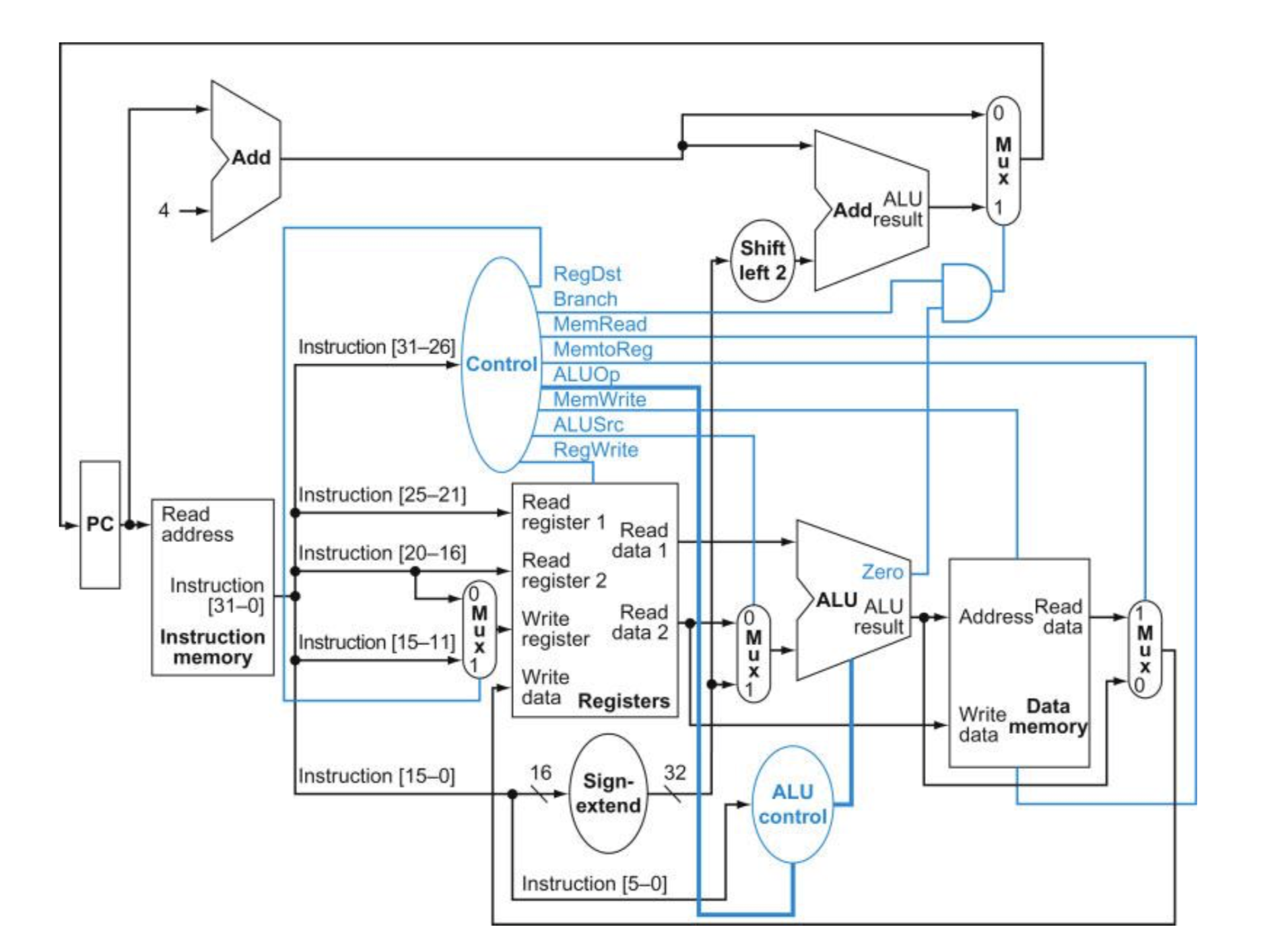
(15 points) Let's take one more stroll down memory lane to visit our
datapath Figure 4.17. As we have noted all along, there's one big
unrealistic aspect of this diagram: the separation of Instruction Memory from Data Memory. This unrealism is
made even worse when we introduce caches.
Of course, you could build a system that works with this separation, but for the reasons outlined
by von Neumann in section 2.5 of his Draft, we don't do that. Modern general-purpose computer systems
put instructions and data into the same memory module.
For this problem, you will show how to modify Figure 4.17 and its operation to accommodate
a single Memory module that encapsulates both main memory to hold data and instructions, and any
number of caches.
This will be somewhat easier than it may sound, because we're going to assume that you
have access to a Memory module that has the following attributes:
- Input: Go (1 bit)
- Input: Address (32 bits)
- Input: WriteEnable (1 bit)
- Input: WriteData (32 bits)
- Output: ReadData (32 bits)
- Output: Finished (1 bit)
- To read from Memory:
- Set and hold Address to the desired address
- Set and hold WriteEnable=0
- Set Go=1 for one clock cycle, then return Go to 0 until it's time to do
the next read or write operation.
- Wait as long as it takes (could be many clock cycles) until Finished=1; at
this time, ReadData will show the resulting data until the next
time Go is set to 1.
- To write to Memory:
- Set and hold Address to the desired address
- Set and hold WriteData to the desired data
- Set and hold WriteEnable=1
- Set Go=1 for one clock cycle, then return Go to 0 until it's time to do
the next read or write operation.
- Wait as long as it takes (could be many clock cycles) until Finished=1; at this
time, WriteData will have been written to the desired location in memory.
That is, you can include a rectangle called "Memory" in your diagram, with the input and output
lines as shown above, but you should not show the internal structure of Memory.
Hand in a modified or redrawn version of Figure 4.17 showing the reorganization required to
implement this multiple-cycle / one-memory datapath. You may add any new logic elements you need, but
try to keep your modifications of 4.17 as simple and minimal as possible. You should also include
a concise explanation of anything that is not obvious from your diagram (e.g. how Control will need
to be modified to make everything work, what assumptions you're making that aren't already stated here, etc.)
Here are a few ideas you might find helpful.
- Each instruction will take at least two clock cycles. During the first clock cycle (or longer,
depending on how quickly Memory responds), the next instruction pointed to by the PC
will get Fetched. Your Instruction Fetch phase should end with the requested instruction being
written into a new "Instruction Register" (a 32-bit rectangle like PC, which will be used to store
the instruction during the remainder of the instruction cycle). After that, at least one
cycle will be devoted to executing the instruction (i.e. reading from registers, going through the ALU, etc.).
For lw and sw instructions, however, there will be another phase of indeterminate length during
which Memory is accessed again.
- Because a single instruction cycle (i.e. Fetch plus Execution) will take at least two clock cycles,
it will be important to modify things so that the PC doesn't change on every single cycle like it
does in Figure 4.17. You might find it helpful to make the Clock line going to the PC explicit. (Note
that in Figure 4.17, we assume the Clock is there, but it isn't drawn in the diagram.)
- You might want to have a little counter/register of some kind that keeps track of which phase of
the instruction cycle you're in right now. For example, one value of the counter might indicate
that we're currently waiting for an instruction to get fetched; another value of the counter might
indicate that we're waiting for a lw read from Memory complete; etc.
- It may take significant effort to get your head around this problem, but the actual changes
don't have to be huge. Much of the existing Figure 4.17 can stay as-is.
(3 points) No need for any more recommendations of books or music or jokes or movies or
anything. Thanks for joining me this term. Have a great summer and beyond.